Astrophotography setups today may become really complex systems. They contain many components (computer, mount, power sources, cameras, sensors, focusers, rotators, dew cap heaters, and more) and all these elements need to be connected to do their job. Electrical connections must be stable and of good quality, but even if we use perfect cables, EMI filters, and good-quality power supply units we may still encounter problems with connectivity and stability – and the reason can be this post-entry villain – the ground loop. It may (but does not need to) cause problems with connection, lost connection errors in random moments, and connection timeouts – to name a few.
Probably many of you are already familiar with voltage drop phenomena. Let us take a look at the very basics of electricity – Ohm’s law.
U = I * R
It says that the voltage in the circuit equals the resistance multiplied by the current.

Let’s assume we have 12V at the power supply unit (PSU) output that powers the camera through the 3m long cable. The cable is not a perfect conductor, it has its own resistance, as well as the connectors. Just for this example, we assume single wire resistance to be 0.2 ohms, so both of them have 0.4 ohms. The camera with cooler set to 100% power drains 3 amperes, so it is now easy to calculate, that the voltage drop over the cables and connectors will be 3 * 0.4 = 1.2 volts. And that gives us 10.8 volts only on the camera – a 10% loss, which is significant. So long story short – keep cables short and connectors clean (there are some cleaning sprays available).

Let us now set the reference point of the voltage measurement – that will be the PSU ground point (black dot at the schematic above). We have 12V at the PSU output, and now we can calculate the voltage drop along each wire in the cable. The wire has 0.2 ohms, so the drop is 0.6V. So at the ground point in the camera, we have 0.6V, and at the positive tip, we have 11.4V. That is perfectly okay for the camera because it does not care about our reference point set in the PSU – it only cares about the voltage difference that it can drain the power from. But that will change in a moment.

Another component in our setup may be a 12V-powered mini PC computer. Since our PSU is capable to deliver 10 amperes we connect the computer to the same PSU. The computer drains 1A on average, and the cable and connectors resistance is 0.1 ohms because the cable is shorter. It is now easy to calculate that the drop is 0.1V and we have 11.9V at the positive tip in the computer power connector, and 0.1V at the negative pin. We still use the same reference which is the ground pin in the PSU. So far so good, both camera and computer work fine, there is some voltage drop for both devices, but still within specifications.
Now we want to transfer images from the camera to the computer, so we connect them with a USB cable. USB cable contains several wires inside that transfer data, but also a ground wire that connects the ground plane of both connected devices. In most devices, the USB ground is connected to the negative pin of the power socket in the device, and the problem begins. As you can see in the simple schematic below in such a scenario the ground signal is connected in two ways to each device. For the camera, we have a direct connection with a power cable, and also another connection with the USB cable and a computer power cable. The same is for the computer – the ground signal is connected directly to the PSU but also with the USB cable through the camera to the PSU. Ground signal creates a kind of loop, and that is called a ground loop.

The problem with a ground loop is the voltage differences at different points in the loop. The ground plane should be a reference, and as long as we connect independent components there is no problem. But since the camera and the computer are using the same PSU, they are not independent anymore.
In the scenario above, the USB cable ground wire connects two points of different voltages, and the USB circuits are not designed to work in such conditions. When both ends of the ground wire of the USB cable have different potentials some additional current flows over that wire. The amount of this current may vary if the load to the camera changes – like when cooling power is increasing or decreasing. Such conditions may cause data transfer errors and connection lost errors as well. It is hard to predict if and when they happen, can be pretty random, and that is very hard to investigate.
Let us take a look at another example.
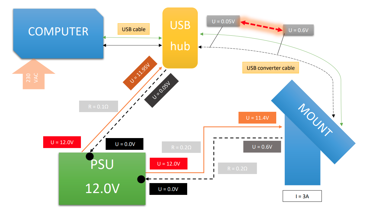
Here we have a computer powered directly from the 230VAC, so there is no common ground problem. But we decided to put an active USB hub on our setup, so we can have a single USB cable from the computer to the setup, and there we split the USB signal to our devices. However, if we power the USB hub from the same PSU (either directly or using some DC/DC converter), then we again will have a ground loop problem. Most active USB hubs (both powered with 5V or 12V) have analog and digital ground connected inside.
The same applies to some dedicated power and USB signal hubs or concentrators, that get both 12V DC power from PSU and USB signal from the computer, and then distribute it over many DC and USB outputs. Unless there is galvanic isolation inside between the digital and analog parts, this kind of device will cause most probably the ground loop.
The most problematic aspect of the ground loops is that they may cause problems, but does not need to.
Your astroimaging setup may work perfectly with the ground loop present. The actual ground loop influence depends on many other conditions:
- how does the computer, hub, camera, or mount deal with such voltage variations
- quality of the cables and connectors (both power and USB)
- changes in the setup
- device drivers
That is why ground loops cause issues sometimes hard to investigate and identify. Your setup may work correctly for some time, but once some connector gets dirty its resistance increases and a larger voltage drop may cause connectivity issues. Or you replace the camera, the computer, or the USB hub with a different model that does not handle the ground loop well and will not work properly. You start to replace USB cables then, get another PSU unit – and that may even help – so you think “well, bad quality PSU”, but the problem is still there, just hidden.
So how to handle the ground loop problem when we suspect it causes issues?
You need to break the loop. It can be done at any point of the loop, but the common solution is to use a separate power supply for different components. It does not need to be a separate PSU for each component (but it can be of course). Two power supply units are usually enough: one for digital components of the astrophotography setup and another one for analog ones. So the first one may power the computer and USB hub. And another one will be for cameras, mount, dew cap heaters, focuser, etc. A simple scenario is presented in the graphics below.

In the example above we still have a USB cable connection that ties the grounds of both the camera and the computer. But the ground loop is not present there because the power supplies of both components are separated.
Since each setup is different it is important to review the power and signal cables and connections and try to determine the ground loop in advance to avoid it. As I already mentioned – the ground loop may cause issues, but does not need to. So perfectly working setup may at some point of the time start to misbehave, and then one can look for problems in many different places, but not spot the ground loop – existing, or a new one created by some changes in the setup.
That was a lot of reading, so summing it all up – what are the usual suspects:
- single power supply for analog (cameras/regulated heaters/focuser/mount) and digital (computer, USB hub) setup components.
- advanced power and USB hubs/concentrators. If there is no galvanic and/or optical isolation inside between the digital and analog parts, then a ground loop is very probable to occur in the setup
- messy cable and connection management. Even if we have many power supplies, but the setup is not properly designed, we can still have ground loops present
And again – the ground loop may, but does not need to cause issues in the setup. But if the ground loop is present in the system and the connection problems start, these are the first suspects, but the last ones we investigate.
Clear skies and clean setups!
Cover photo by israel palacio on Unsplash
